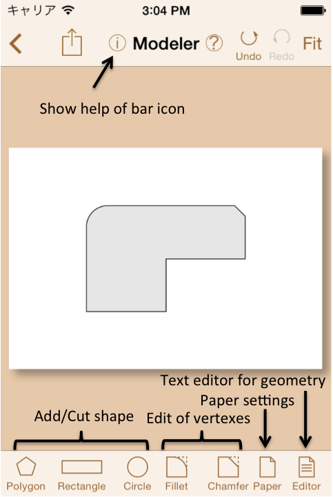
Fig.4.1 Modeler's view
Fig.4.1 shows a main view of Modeler.
Two dimensional geometry is inputted on a virtual paper. Icons for adding/cutting geometry, editing vertexes or paper settings are placed on the toolbar.
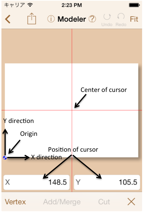
When a geometry input command (Polygon, Rectangle, Circle) is tapped,
cursor, origin mark and position of cursor will be shown on the view as shown in Fig.4.2.
The center of cursor is always at the center of view.
The cursor position can be moved by scrolling the view,
or by enter coordinate value.
The initial position of origin on the paper is placed at left-bottom corner.
It can be changed in Paper command.
and position of cursor will be shown on the view as shown in Fig.4.2.
The center of cursor is always at the center of view.
The cursor position can be moved by scrolling the view,
or by enter coordinate value.
The initial position of origin on the paper is placed at left-bottom corner.
It can be changed in Paper command.
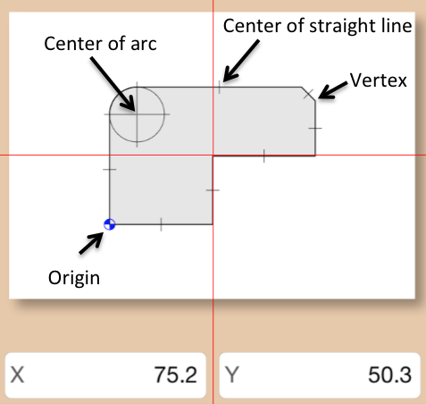
Auxiliary lines representing the center of line or arc are shown in the input state of geometry (Fig.4.3). These are called "Hot Spot". When a hot spot is tapped, the view will scroll until to be coincident the hot spot to the cursor position.
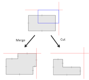
A model geometry is create by adding, merging or cutting with basic geometries like polygon, rectangle or circle as shown in Fig.4.4. And fillet or chamfer operation can be applied on the vertexes of the geometry. Please tap a vertex after entering the dimension of chamfer or fillet.
You can edit geometories with text editor by tapping  .
.
The geometry data format is as followings.
The text file is encoded by UTF8 unicode.
Space or line break characters are recognized as the separator of data.
One line is handled as one record.
A line with @ character at the head means the start or end of a block.
A block begins from a block header with @ character and the block name.
@end means the end of block.
In the geometry data, there are only boundary blocks. Two kind of line element - straight line and arc, are defined in the boundary block. Only a line element can be laid on a data line. Each line includes an end point of a line element. Outline of geometry is defined with counter-clockwise, hole is defined with clockwise.
A straight line is defined with its end point ([X],[Y]) and a symbol "L". The first stright line in a boundary block is drawn from the last point of the block.
[X] [Y] L
@boundary
  0 0 L
  100 0 L
  100 100 L
  0 100 L
@end
By the way, the symbol "L" can be removed.
An arc is defined with its end point ([X],[Y]), a symbol "A", the center of arc ([CX],[CY]), a radius ([R]), and a direction of rotation "ccw"(contour-clockwise) or "cw"(clockwise).
[X] [Y] A [CX] [CY] [R] ccw/cw
@boundary
  10 0 A 0 0 10 ccw
  0 10 A 0 0 10 ccw
  -10 0 A 0 0 10 ccw
  0 -10 A 0 0 10 ccw
@end
Circles generated by the modeler are represented with four divided arcs.