,
the intensity of image is changed like painting software,
and the mesh is generated with specified minimum and maximum element size in Mesh command
,
the intensity of image is changed like painting software,
and the mesh is generated with specified minimum and maximum element size in Mesh command .
.
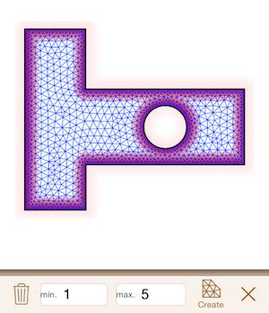
In Mesher, A FEM mesh consisted of triangular patches is generated from the model geometry.
The distribution of mesh roughness (element size) can be specified with the intensity of a mesh density image.
In the mesh density image command,
the intensity of image is changed like painting software,
and the mesh is generated with specified minimum and maximum element size in Mesh command.
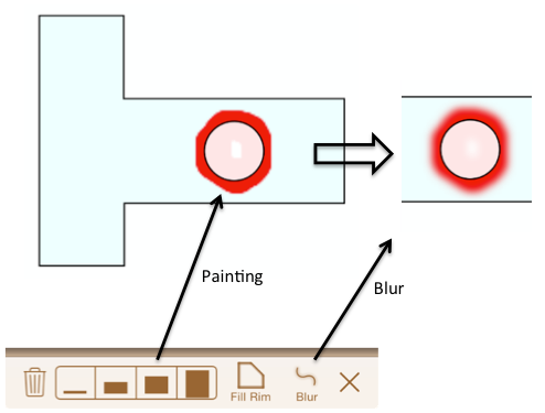
As shown in Fig.5.1, with brush command , paint the domain for becoming finer than around.
If red color is stronger, mesh will be finer.
After painting, to avoid the sharp change of mesh density around the boundary between painted part and not painted part, the applying of blur operation
, paint the domain for becoming finer than around.
If red color is stronger, mesh will be finer.
After painting, to avoid the sharp change of mesh density around the boundary between painted part and not painted part, the applying of blur operation is recommended.
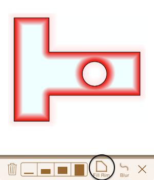
The inside of model's rim can be filled with  command.
The color gradations is dark near the rim and is thin away from one (Fig.5.2).
command.
The color gradations is dark near the rim and is thin away from one (Fig.5.2).
In the mesh command, a mesh is generated with specified minimum and maximum element size by  .
The maximum element size is used if the density image is uniform.
Please keep in mind that the generated element minimum or maximum size may not be equal to the specified value.
.
The maximum element size is used if the density image is uniform.
Please keep in mind that the generated element minimum or maximum size may not be equal to the specified value.
The mesh generation may not be completed, since of various reasons, for example the space in model is narrower than minimum element size. In the case, please retry after changing the minimum and maximum element size.
The time for mesh generation will be long when the specified element size is too small. In this case, since generated mash has many elements and nodes, please caution about that the computation load and memory consumption in the after operations(adding analysis condtions, FEM analysis, visualization, etc.) will be higher.