.
.
In Conditioner, constraint conditions and load conditions are attached to the mash, and, material properties and analysis type are specified. A constraint condition or load condition is appended after selecting nodes or elements in advance.
In this application, constraint and load conditions are applied on boundary only. As load condition, concentrated load appied on node, and distribution load on element edge on model's boundary (boundary load) can be spacified.
Caution) For executing FEM analysis successfully, constraint conditions in each X and Y direction are necessary at one place at least for each direction.
In the case of iPhone/iPod Touch, open selection command by tapping Select icon. In the case of iPad, the functions of selection command are displayed on the lower toolbar.
Nodes and element edges on boundary of mesh can be selected only.
 begins selection.
The function of each item is as followings.
begins selection.
The function of each item is as followings.
Whether new selected nodes/edges will be added to (+) or removed from (-) already selected nodes/edges,
is specified with .
It is impossible to selection with specifying whether node or edge. Nodes or edges in the selection are used corresponded to the type of boundary conditions.
All selections are cleared by  .
.
Select nodes in advance.
Open the list of constraint conditions with  .
.
Constraint conditions will be attached to selected nodes with  .
At that time, selected edges are ignored.
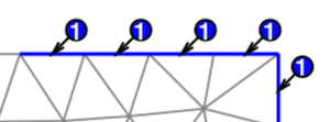
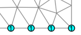
The index of constraint condition is displayed at the nodes attached constraint condition as shown in Fig.6.1.
.
At that time, selected edges are ignored.
The index of constraint condition is displayed at the nodes attached constraint condition as shown in Fig.6.1.
In the each item of list of constraint condition, the left field shows an index of constraint condition, ΔX and ΔY shows a value of enforced displacement in each direction. FREE is shown when ΔX or ΔY field is empty. This means that there is no constraint condition in this direction.
Select nodes in advance.
Open the list of concentrated (nodal) load conditions with  .
.
The concntration load is applied on the selected nodes with .
In that time, selected element edges are ignored.
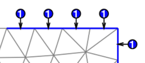
The number at the left of each row in the list means the index of concentrated load. The value of load in X or Y direction is specified with fx or fy field.
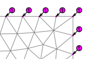
The index number is shown at the node with concentrated load condition as shown in Fig.6.2. The direction of arrow means the direction of load.
Select edges of element in advance.
Open the list of distributed load conditions with  .
.
Distributed load condition is applied on selected edges with .
In that time, selected nodes are ignored.
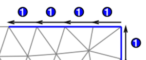
The number at the left side of the list means the index number of distributed load conditions.
Load type is selected with 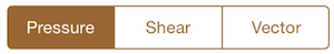 .
These meanings are as followings.
.
These meanings are as followings.
The field specifying load value is changed by load type. The load value is specified with w field when Pressure or Shear is selected. Px and Py field are used when Vector is selected.
The load value is specified with value per a unit length. The multiply value by material thickness will be used in FEM analysis.
As shown in Fig.6.3, the index numbers are displayed at element edge with distributed load condition. And, the vector representation is changed by loading type.