KansuImager
Filter Creation Manual
Second Edition
Oct. 20, 2018
(C)2018, Noboru Imai
Contents
- Abstract
- Usage
- Coordinate System
- Variable
- Equation
- Grammer
- Mathematical Function
- Logical Function
- Σ, Π Operation
- System Function
- Pixel Value Function
- Built-in Filter
- User Defined Filter
- Drawing Settings
- Drawing Function
- Face Detection
- Example of Filter Design
Abstract
Oct. 20, 2018
(C)2018, Noboru Imai
- Abstract
- Usage
- Coordinate System
- Variable
- Equation
- Grammer
- Mathematical Function
- Logical Function
- Σ, Π Operation
- System Function
- Pixel Value Function
- Built-in Filter
- User Defined Filter
- Drawing Settings
- Drawing Function
- Face Detection
- Example of Filter Design
Abstract
A basic image converting method is to define color converting functions for each pixels. At that time, RGB, XY, or Shader mode is selected. Under RGB mode, functions to decide color value are defined for each Red, Green or Blue color component. Under XY mode, functions to decide X or Y position on a original image are defined. RGB mode is mainly used for design of color converting filter, XY mode is mainly used for design of deformation filter. Shader mode is used to convert images by GPU with shader language (a kind of OpenGL GLSL). Please refer Shader Mode Manual to coding method.
In the converting function, variables or constants to get current pixel location or image size, math functions like sin/cos, or filter functions like Gaussian filter can be used.
User can define parameters and equations to set value to it. The parameters can be referred in the image converting functions.
There are functions to be used for design of linear filter.
As the other special functions, IF function to switch calculating equations under the condition, break function to break processing forcibly, line/circle drawing functions, face detecting function, and etc. are equipped.
NOTE
This app needs more processing time than the other commercially available photo effect app, since an image is converted with parsing user defined function at each pixels. Therefore, in filter design stage, it is recommended that small size images are used for test. You can resize image with Resize in the bar button Convert.
Usage
Parameter & Equation
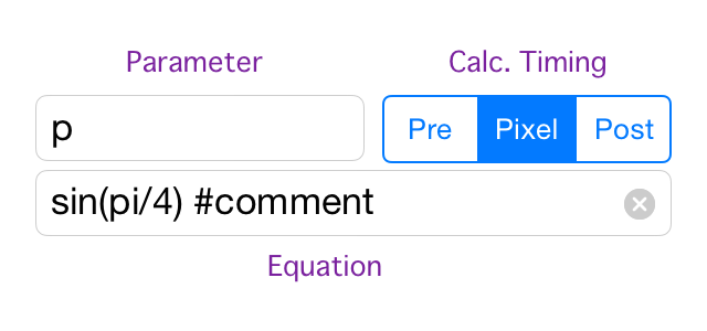
The value of parameter is decided at the timing of pre-processing, in-processing, or post-processing. In the substitution equation, the other parameter can be referred.
If the parameter field is empty, the calculation executes and the result is ignored. It is useful for execution of drawing function.
The calculation timings are followings.
- Pre : prevous of converting
- Pixel : just before each pixels conversion
- Post : after all conversion process
In the each calculation timing, the order of calculation is the same as definitions order. The previously defined parameters can be referred in a equation.
Pre or Pixel parameters can be referred in color or coordinate conversion functions.
In Shader mode, only Pre parameters can be used. Please refer Shader Mode Manual for more information.
The values of Post parameter are shown after image conversion. And since these are copied to the pasteboard, you can copy it to the other app like memo.
Please refer Equation for the equation definition method.
Mode
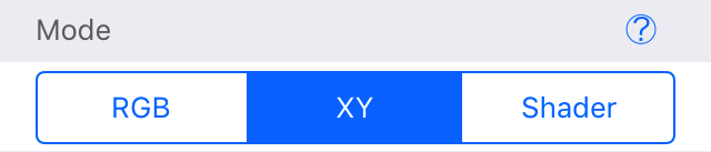
For image conversion, RGB, XY, or Shader mode is selected.
- RGB : conversion with color conversion function
- XY : conversion with X, Y coordinate conversion function
- Shader : conversion with shader language
Function at Pixel (x,y)
In this section, the conversion functions for each pixels are defined. The editing fields are changed dependent with mode selection. For RGB, Red,Green and Blue are shown. For XY, X and Y are shown. For Shader, an editor field of Shader are shown.
By the way, you can know the current location with x and y parameter. For more detail of parameter, please refer Parameter.
Red, Green, Blue
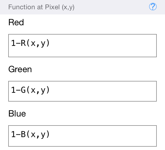
Color conversion functions are defined for each color component. If the field is empty, the original image color component is copied.
A color value is a real number with [0,1] range.
The original image color can be get with R, G, or B function.
X, Y
Coordinate transfer functions are defined in the fields.
Calculating equations for the position of previous of conversion are described. The color at position of previous conversion is copied to the current position(x,y).
Please refer Equation for definition method of equation.
Shader
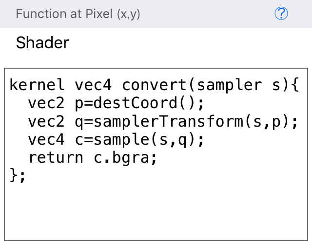
A cord with iOS custom filter language based on OpenGL Shader Language (GLSL) is required. Since it be compiled to GPU machine language and executed with parallel operation, very fast conversion is expected.
However, since it is a processing system completely different from the RGB/XY mode, features available on RGB/XY mode like parameters, equation definition methods, operator, or face detection can not be used. Shader mode is useful to learn shader language or when high-speed conversion is required.
Please refer Shader Mode Manual for the description method of Shader mode.
Range Out Mode
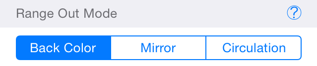
The method of color decision is specified when a point on outside of image area is referred to get color.
- Back Color : background color is used.
- Mirror : turned back at the boundaries.
- Circulation : circulation connection at each boundaries.
Background
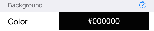
Specify background color when Back Color is selected for Range Out Mode.
Coordinate System
The origin is at top-left corner. The right hand direction is X plus axis, and the lower direction is Y plus axis.
Parameter
Naming Rule
Character in parameter's name is alphabet, underscore '_' or number.
It must be start from alphabetic or underscore.
This is case sensitive.
Parameters with the same name of function can be used.
Built-in Parameter and Constants
- x : current X location on image
- y : current Y location on image
- W : image width
- H : image height
- pi : constant π=3.1415...
- π : constant π=3.1415...
Equation
Grammer
Arithmetic expression with brackets () can be defined. The following operators are available.
- + : addition
- - : substraction
- * : multiplication
- / : division
When '#' is inserted in a equation, the tokens after this is ignored as comment. However, the comment in break function will be shown after the process is stopped.
Built-in functions are shown as the followings.
Mathematical Function
In a mathematics funcion, C language function with the same name is called.
| cos(θ) | cos function |
| sin(θ) | sin function |
| tan(θ) | tan function |
| acos(t) | inverse of cos, t=a/r |
| asin(t) | inverse of sin, t=b/r |
| atan(t) | inverse of tan, t=b/a, return range:[-π/2,π/2] |
| atan2(b,a) | inverse of tan, return range:[-π,π] |
| ln(x) | natural logarithm: ln x |
| log(a,b) | logarithmic function: logab (=ln(b)/ln(a)) |
| log10(x) | common logarithm: log10 x |
| exp(x) | exponential function: ex |
| pow(x,a) | power function: xa |
| abs(x) | absolute function: |x| |
| sqrt(x) | square root |
| floor(x) | discard decimals |
| fmod(x,y) | remainder of x÷y |
Logical Function
Logical functions are equipped. Non zero value is regarded as true. zero is regarded as false.
| IF(fg,x,y) | judging function return x when fg is TRUE(fg≠0), or y when fg is FALSE(fg=0). |
| NOT(fg) | negative function:returns 0 when fg is TRUE, or 1 when fg is FALSE. |
| EQ(a,b) | comparison: a==b |
| LT(a,b) | comparison: a<b |
| LE(a,b) | comparison: a≤b |
| GT(a,b) | comparison: a>b |
| GE(a,b) | comparison: a≥b |
Σ, Π Operation
SIGMA function is an implementation of summation Σ. PI function is an implementation of infinite product Π. These can be also used for repetitive processing.
| SIGMA(i,i0,i1,eq) | 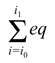 |
| PI(i,i0,i1,eq) | 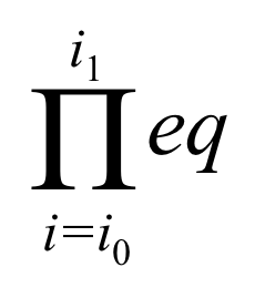 |
System Function
break function is implemented to control execution state. It is used with IF function to interrupt process forcibly. For example, it is used in a process with face detection. If no faces are detected, the process is stopped with following equation.
A parameter to be used in an iterative operation is defined at the first argument. Its name must be different of user defined parameters. The second argument is the initial value, and the third is the end value. A equation for the iterative operation is placed at the fourth argument.
IF(EQ(faceCount(),0),break(),1)#No Face
| break() | forced interrupts process. # comment is shown after the interruption |
Pixel Value Function
Functions getting pixel value at specified point on original image are followings.
| M(x,y) | monochrome value |
| R(x,y) | red component |
| G(x,y) | green component |
| B(x,y) | blue component |
| meanColor(cid,x,y,w,h) | getting average value in rectangular area.
(x,y):left-top corner, w:width, h:height cid:0-monochrome,1-red,2-green,3-blue component |
Built-in Filter
There are functions to get filtered pixel value.
| gaussF(s,cid,x,y) | Gaussian filter (blur filter) s:blur strength,(0,5] real number |
| averageF(s,cid,x,y) | moving average filter (blur filter) s:moving length,(0,8] integer |
| sobelF(cid,x,y) | Sobel filter (edge detection) |
User Defined Filter
You can design linear filters yourself.
First, in Pre timing, execute function opX (X is [2,5] integer) that defines a operator of linear filter, and get the operator index. Then, call filter function in each color conversion function in RGB mode.
| op2(e00,op01,e10,e11) | 2x2 size oparator. |
| op3(e00,...,e22) | 3x3 size oparator. |
| op4(e00,...,e33) | 4x4 size oparator. |
| op5(e00,...,e44) | 5x5 size oparator. |
There is a function to get filtered pixel value with user defined operator.
| filter(oid,cid,x,y) | apply linear filter oid:operator index cid:0-monochrome,1-red,2-green,3-blue (x,y):coordinate on origianl image, return:[0,1] real number |
Drawing Settings
Drawing setting functions are used to control drawing conditions. These must be called in Pre or Post timing. Don't fill the parameter fields to avoid presentation of parameter value.
| setLineColor(r,g,b,a) | line color. Range of color value is [0,1] real number. r:red component g:green component b:blue component a:alpha component (0:transparency,1:opacity) |
| setFillColor(r,g,b,a) | fill color |
| setLineWidth(w) | line width w:width[dot] |
| setAntiAliasing(fg) | On or Off of anti-aliasing fg:1-On,0-Off |
Drawing Function
Drawing functions must be called in Post timing. Do not fill parameter field to avoid presentation of parameter value.
| line(x0,y0,x1,y1) | stroke line element between (x0,y0)-(x1,y1) |
| circle(x,y,r) | stroke circle at center (x,y) with radius r |
| fillCircle(x,y,r) | fill in circle |
| rectangle(x,y,w,h) | stroke a rectangular shape with left-top (x,y), width r and height h |
| fillRect(x,y,w,h) | fill in rectangular shape |
Face Detection
You can get information for face existence and position with face detection functions. Call face detection functions in Pre or Post timing.
| faceCount() | number of detected face |
| faceX(fid) | X coordinate of face center |
| faceY(fid) | Y coordinate of face center |
| faceWidth(fid) | face width |
| faceHeight(fid) | face height |
| faceItemExist(fid,item) | detection of face parts 1-detected,0-not detected |
| faceItemPosX(fid,item) | X coordinate of face parts |
| faceItemPosY(fid,item) | Y coordinate of face parts |
| bigFaceID() | face index with largest face -1:not detected |
Example of Filter Design
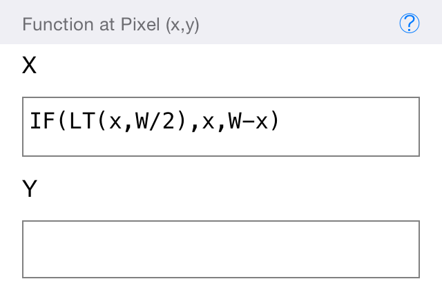
Mirroring
Following is a creating procedure of mirroring filter that copies left half side of image to right half side.
- Create new filter.
- Select XY as mode.
- Describe following in X function.
IF(LT(x,W/2),x,W-x)
In XY mode, a pixel at the specified position on original image is copied to the current position (x,y). X and Y function are iteratively called for each pixels. In this case, since mirroring process is applied for only X coordinate, Y function field is blank.
LT(a,b) function returns 1 in a<b, or returns 0. In this example, since W is image width, when x<W/2 ie x points a left side location for the center, it returns 1, or not, return 0.
IF(a,b,c) function executes b, if a≠0, or if a=0, it executes c, and return the result. Therefore, in this example, if x is at left side, x is returned, if x is at right side, W-x is returned.
Subtractive Color Processing
As an example for usage of parameter, a monochrome subtractive color filter is created.
- Create new filter.
- Tap Add Parameter for adding new parameter.
- Type m as parameter name, specify Pixel, and describe in equation field as following.
M(x,y) - Tap Add Parameter.
- Type c as parameter name, specify Pixel, and describe in equation field as following.
0.2*(U(m)+U(m-0.2)+U(m-0.4)+U(m-0.6)+U(m-0.8))
or
0.2*SIGMA(i,0,4,U(m-0.2*i)) - Select RGB as mode.
- In Red, Green, Blue function field, describe as following.
c
M(x,y) function returns a monochrome color value of original image at specified position. x and y are set coordinate of current position. The result of M function is set to parameter m in order to executing speed-up and visibility of filter design.
U(x) is a step function. It returns 0 when x<0, or returns 1 when not x<0. The value of parameter c will change in a stepwise manner.
Since all Red, Green and Blue function returns the same value, a monochrome image will be get.
Unsharp
As an example for usage of user defined linear filter, a filter to recover sharpness of blur image is created as followings.
- Create new filter.
- Define parameter a specifying strength of sharpness with Pre timing, and set arbitrary value that is non zero positive integer value (2 is recommended).
- Define parameter oid with Pre timing, to set operator index, and describe following in equation field.
op3(0,-a,0,-a,1+4*a,-a,0,-a,0) - Select RGB as mode.
- Describe followings in each Red, Green, Blue function field.
filter(oid,1,x,y) #Red
filter(oid,2,x,y) #Green
filter(oid,3,x,y) #Blue
- Select Mirror as Range Out Mode.
A operator is defined with matrix elements described in column priority. op3 used in this expample is a 3x3 matrix having nine elements. Since the return value is an identifier, it is kept in parameter oid.
filter(oid,cid,x,y) applies user defined operator on the specified point on original image. oid is a operator's identifier. cid specifies the applied color component, 0 is monochrome, 1,2 and 3 means red, green and blue. (x,y) specifies the center of operator applying area. In the case of op3, the area has 3x3 pixels. When pixels at outer of image are referred, the condition specified with Range Out Mode is applied.
Face Detection
In this example, face detection is tried, and circles are drawn on detected faces.
- Create new filter.
- Define parameter fn with Post timing.
faceCount() - Define four nameless parameters with Post timing, and describe as followings for each parameter.
- IF(EQ(fn,0),break(),5) #no face
- setLineColor(1,0,0,1)
- setLineWidth(2)
- SIGMA(fid,0,fn-1, circle(faceX(fid),faceY(fid), faceWidth(fid)/2))
- All conversion functions are blank.
In the nameless parameter 1, when the face count fn is zero, break function is called then the process is interrupted. After this, the comment “no face” is represented.
The nameless parameter 2 and 3 specifies line color and width.
In the nameless parameter 4, iterative process is realized with SIGMA function.
At the first argument of SIGMA function, a name of control parameter to control repeat number is described. When the parameter is already defined, the value is overridden. If the parameter is not defined, new parameter is defined. The parameter can be referred in the later equations. In this example, fid is face identifier.
At the second and third argument of SIGMA function, the initial and end value are described. The value of control parameter is incremented after each process of iteration. In this case, since fn contains number of faces and the face identifier begins from zero, the initial value is set 0 and the end value is set fn-1.
In the last argument of SIGMA function, an iteratively executed equation is described. In this example, circle function is called.
In the arguments of circle function, faceX and faceY function to get face position, and faceWidth getting face width are called. Since fid is used in each function, circles are drawn on the all faces.
Because all conversion function fields are blank and all parameters are defined with Post timing, after the original image is copied, circles are drawn on the image.
⬆︎